Rack Mount Prototype to Production
Electronic Enclosures, Inc. (EEi) brings 4+ decades of expertise to provide the chassis design through CDR and prototypes, with the end goal of production and integration of your custom 19” rack mount enclosure system. Thermal design and EMC are included in this process.
Our typical customer has their core competency in the electronic design, software, and production of high-technology electronics within their market. EEi completes your rack mount system to the level you specify. EEi’s production environment is for a high mix of low to medium-volume custom rack mount chassis and card cage systems.
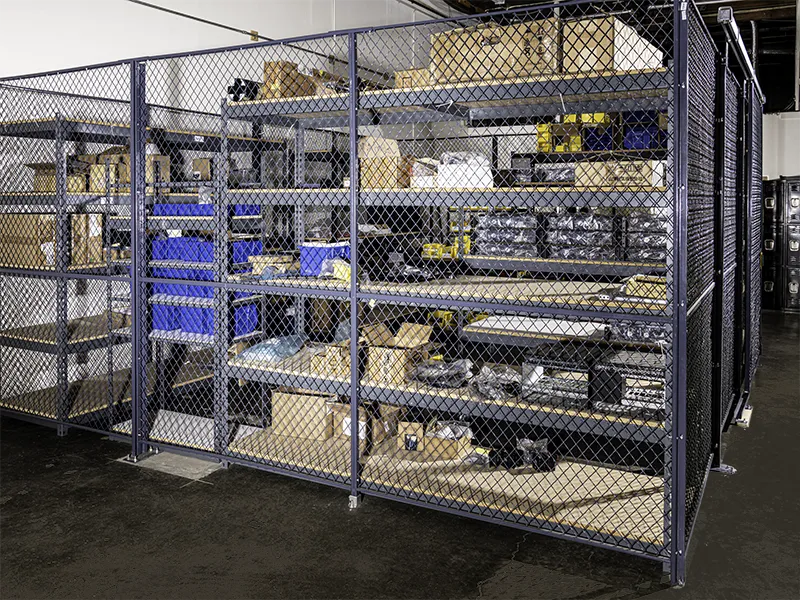
We do design and produce PCBAs, which are typically limited to power distribution, user interface, and I/O, we don’t have a high-level EE engineering team to keep up in any specific market, so we keep it simple. We do our own kitting in-house to ensure all boards meet our anti-counterfeit policy. This also provides for faster resolution of supply chain issues, should they arise.
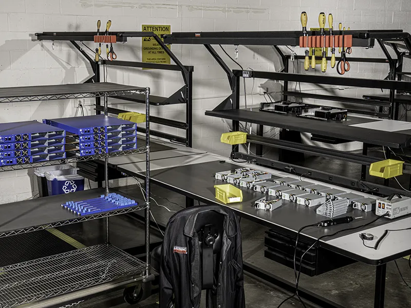
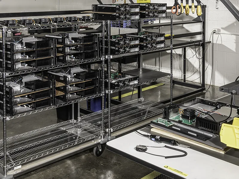
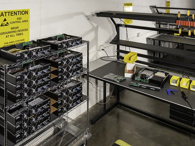
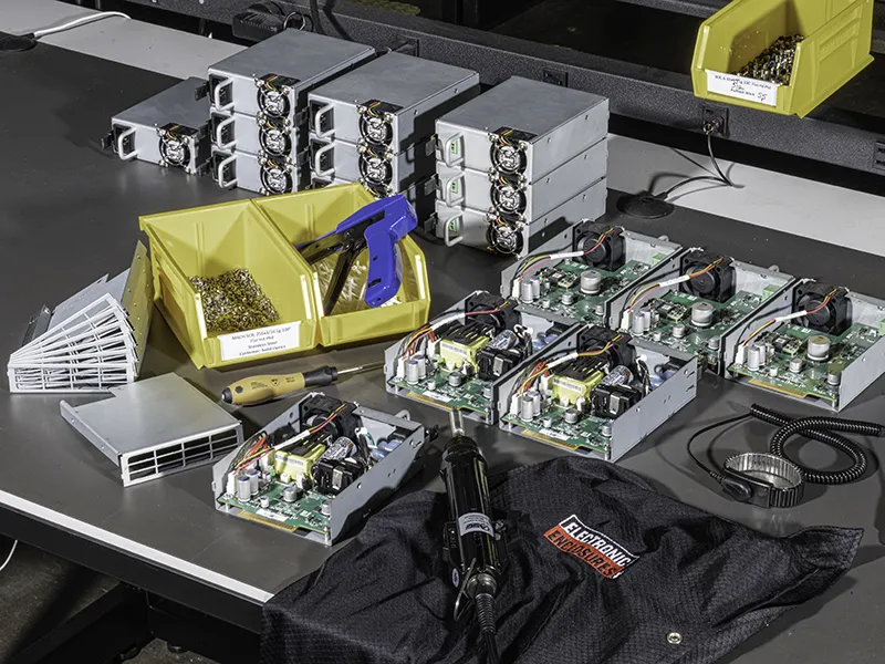
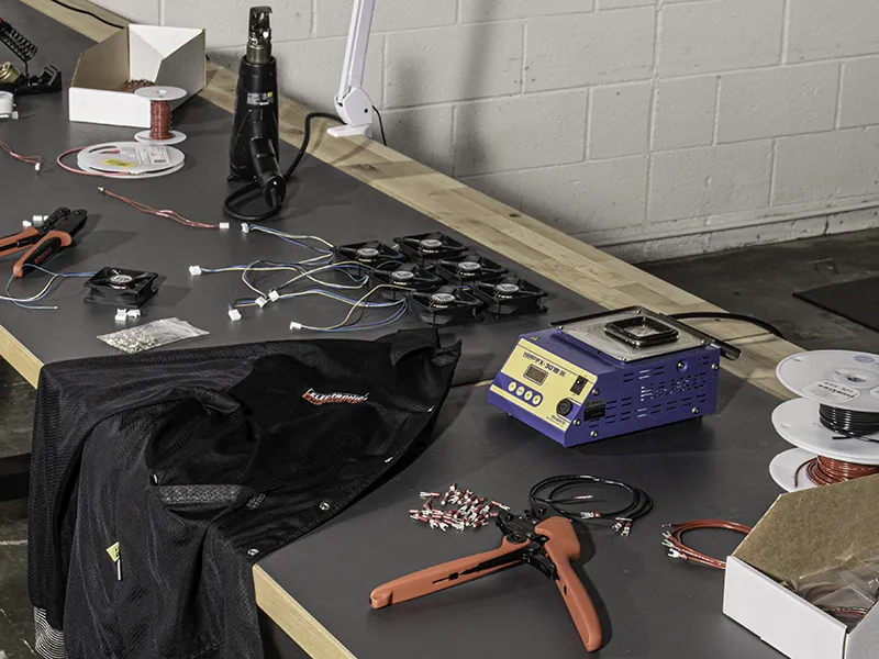
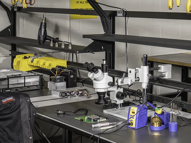
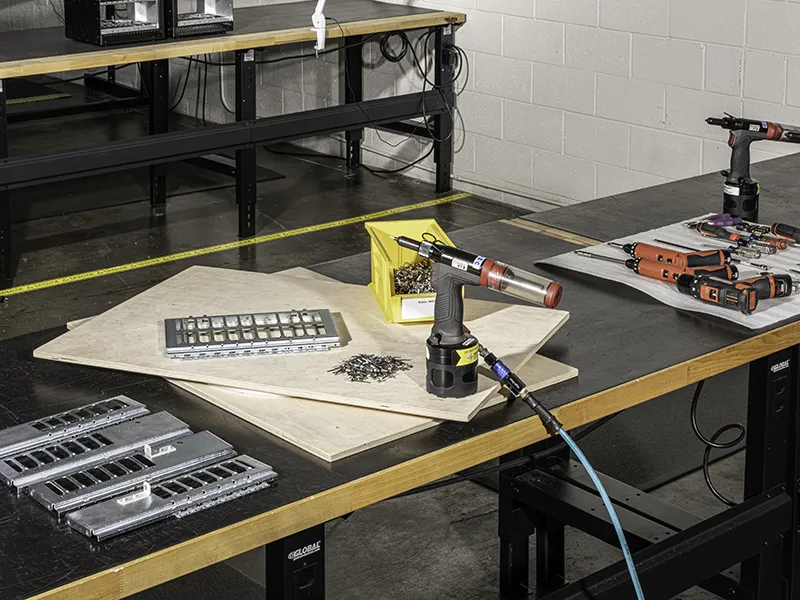
The rack mount chassis’ mechanical assembly is performed in one department and is transferred to our ESD-compliant area for electronics integration. This may include system motherboards, backplanes, plug-in cards, hot-swap power supplies and their power distribution PCBA, user interface and I/O PCBAs, cable and wire harnesses, fans and other thermal components, etc. If contracted, our customer ships the high-level boards to us, and they’re kept in our consignment cage until integration.
Board assemblies meet J-STD-100 and IPC-A-620, while wire harnesses and cable assemblies are produced to IPC/WHAM A-620.