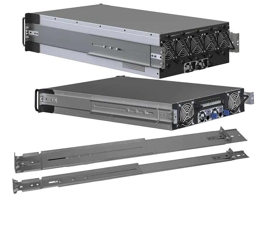
Injection Molded Components used in
the Design of Custom Rack Mount Systems

Electronic Enclosures, Inc. (EEi) also offers injection molded plastic parts (most often used over other plastic manufacturing methods) in our rack mount enclosures. Plastic parts may be large front panels to add aesthetics and branding features or small light pipes.
Molded plastic offers incredible flexibility for developing a brand, adding increased perceived value or industry/product differentiation through unique aesthetics, styling, texture, color and form.
rack mount injection molding

A 3 part injection molded front panel (with silk-screen graphics), keypad & clear protective lens.


Plastics are available with a multitudes of properties:

  • Ultra Tough to Flexible
  • Inherent EMI Shielding
  • Flame Retardant
  • Severe Chemical Resistance
  • Thermally Conductive (Comparable to Aluminum)
  • Electrically Conductive, while Most Often Electrically Insulative

Most can be color matched to corporate identity colors or marketings requests.
EEi has extensive design and manufacturing experience for insert molding. We can provide parts from either single-shot or multi-shot molds for insert molding of other plastic parts, like light pipes, logo badges and threaded inserts.
Non-EMI shielding plastics may be made with copper or ferrous coatings or through vacuum metallization.
Plastic assemblies may be mechanically joined with fasteners, ultrasonically welded, heat staked or bonded.
rack mount pressure form

Shown here is a 7U front panel using pressure formed plastics for a Telco rack mount system.


When adding plastics to your enclosure, either for aesthetics, cost savings, weight savings or functionality, there are optional plastic production methods suitable to a variety of production levels, large and small. We have also utilized pressure-formed plastics, RIM molding (reaction injection mold) and machined plastic components. Each of these methods has their own appropriate application, production methods, tooling and production costs. With our background in tooling, production and design we can recommend the process best suited to meet your program requirements and projected production levels.

Know Tooling Before Design

In our opinion tool design and part design go hand in hand as they closely impact each other. This greatly influences many things, tool cost and maintenance, cycle time, part quality, flatness or straightness, aesthetics and most of all your reoccurring part costs. For instance, what in a part design causes, curl or potato chipping and what can be done about it? Here are some other important examples:

Ejection 1: Being able to design for a standard ejector box with pin and blade ejection is greatly preferred over two-stage, air, pluck or reverse. The further from standard one gets the higher the tooling cost and maintenance.

Ejection 2: When a part sticks in its mold and won’t eject properly and consistently without cosmetic damage, how does one resolve this? Could the part design have eliminated this from the beginning?

Slides: There are many types of slides. Each type has limitations that can affect part design. What type features and proximity to other features impacts slide type and design. This in turn affects mold cost and maintenance. Can an attractive design that meets your requirements be produced without the need for cost adding slides?

Gating: This too is important in terms of its type and placement. Edge, fan, tab, pin or sub-gate and then hot tip, valve, etc., for which type does one design? Will it result in unwanted or unsightly gate trim, blush or knit lines in critical or highly aesthetic areas? An improperly selected gate type or placement will negatively affect your parts cosmetic, aesthetic appearance or negatively affect your products perceived value.

Depending upon part geometry and optimal gate location, some gate types hide gate trim, others do not. Some can hide gate blush, others do not – and what else can proactively be done in design to minimize or hide gate blush?

Runners: There are as many types of runners as gates: hot, cold, insulated, hot drop, etc. What does one design for?

Draft & Texture: These two go hand-in-hand. These seemingly simple choices, if done wisely, will result in great looking parts from day one. If incorrectly specified this can result in cavity modification, parts sticking in the mold, visible gate blush, knit lines and unsightly drag marks on the side of your parts.

Water Lines: Understanding how mold temperature and its control affects the finished part geometry, cycle time and cost. Planning for the future is also critical here as adding a future feature may not be possible without remaking a core or cavity. Planning ahead and understanding water lines (along with ejection) can eliminate or minimize the risk.

Mold Type: Should you specify an SPI mold class and what does that mean? What is appropriate for your applications?

  • MUD
  • 2 Plate or 3 Plate
  • When do you need hydraulic side pulls?
  • When do you need a collapsing core?
  • What about mold material: Aluminum, P20, H13, S7, NAK80, etc.

Aluminum may seem cheaper but not necessarily, and it comes with risks.

Some choices are aesthetically acceptable and others not. Other choices result in high mold and/or part costs while others not. We frequently hear “I am a product designer, I don’t need to concern myself with the tooling. That’s the tool designer’s job” In our opinion, for managing tool costs, part costs and appearance, the part designer needs to be thinking about every aspect of the tool design with every part geometry decision they make. Leaving decisions like these up to the tool designer and builder (most often off-shore) can be hazardous to your part’s appearance and cost.

EEi engineering group designs your parts, oversees and directs tool design, manages tool building and production schedule . AND, we’ll assemble the parts to the rest of your system enclosure.  We make it seamless, easy and brilliant.

  • This field is for validation purposes and should be left unchanged.